
[email protected] Sales: +91 96014 44111 Service: +91 96013 33888
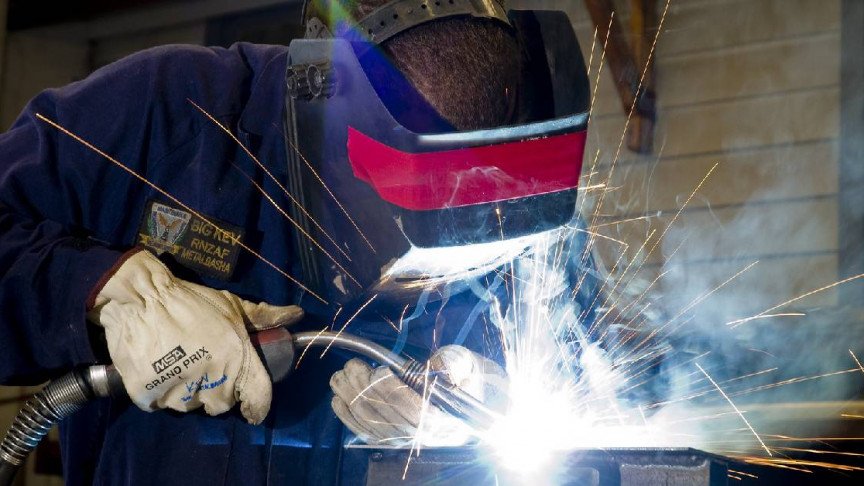
Industrial Welding Rotator in heavy vessel manufacturing workshop
ISO 9001:2015 Certified Manufacturing

Industrial Welding Rotator Engineering & Global Procurement Master Guide

High-precision turning rolls from 5T to 500T payload capacities. Engineered with anti-drift control, stepless VFD rotation, and seamless SAW automation integration.

500 Tons
Max Turning Payload
±0.5 mm
Axial Drift Precision
22,600+
Global Installations
21+
Years R&D Excellence
Advanced Power Sources Limited · Automation Division

Mastering the Mechanical Dynamics of Heavy Vessel & Pipe Fabrication

In modern heavy manufacturing, an Industrial Welding Rotator (commonly known as turning rolls) is far more than a simple material handling mechanism. It is a critical, high-precision automation unit that directly dictates circumferential weld seam geometry, interpass deposition consistency, and total cycle time efficiency.

Whether you are fabricating thick-walled pressure vessels compliant with ASME Section VIII, monopile foundations for offshore wind turbines, or high-pressure cross-country pipelines, rotational instability or axial drift can lead to catastrophic weld defects, excessive joint grinding, and severe project cost overruns. Advanced Power Sources Limited (APS Welding) manufactures industrial welding rotators designed to eliminate mechanical runout, absorb dynamic shell eccentricity, and maintain stepless rotation speeds down to fractional millimeters per minute.

  • Payload capacities spanning 5 metric tons to 500+ tons
  • Self-aligning (SAR) and Conventional (CR) mechanical designs
  • Anti-creep hydraulic axial drift control options (±0.5 mm)
  • Heavy-duty 90 Shore A polyurethane, rubber, or forged steel wheels
  • VFD AC inverter motor drives with closed-loop tachometer feedback
  • Direct closed-loop integration with Submerged Arc Welding (SAW) systems
Get a Quote
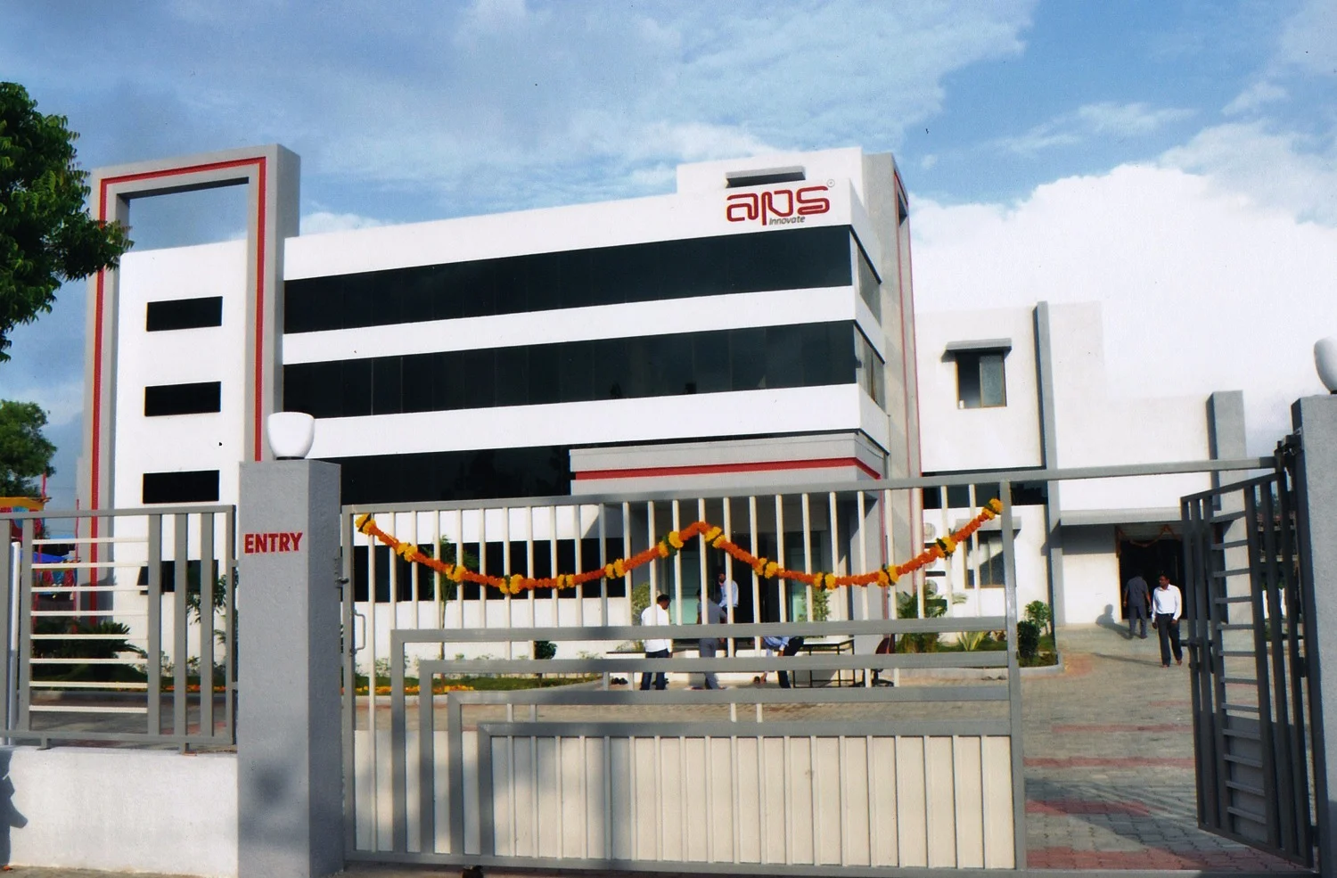
APS Engineering team assembling heavy industrial welding rotators in Gujarat factory
20+ YearsIn-House Engineering Excellence
Engineering Insights

Classifications & Core Mechanical Architecture

Understanding the structural physics and mechanical variations between rotator types is paramount for selecting the optimal configuration for your fabrication shop.

Self-Aligning Rotators (SAR Series)

Engineered with dual-swivel wheel brackets on both drive and idle units, SAR systems dynamically adjust wheel angle to automatically fit varying shell diameters without manual mechanical adjustments. This dramatically cuts setup time in multi-diameter job shops.

Conventional Turning Rolls (CR Series)

Built upon robust fabricated steel beds with manual bolt/pin or motorized lead-screw wheel bracket adjustment. Conventional rotators offer supreme structural rigidity, making them the preferred choice for long-term production of uniform vessel shells and super-heavy payloads exceeding 100 Tons.

Anti-Creep & Anti-Drift Mechanics

Vessel "axial drift" or longitudinal creep occurs due to shell spiral geometry, wheel tilt misalignments, or uneven weight distribution. APS anti-drift rotators utilize active hydraulic actuators beneath the idle unit wheels to counteract axial displacement in real time, keeping seam movement within ±0.5 mm.

Wheel Material Science: Polyurethane vs. Rubber vs. Steel

Selecting the correct roller wheel coating is vital to prevent workpiece contamination, premature tire degradation, and surface slippage:

  • Polyurethane Tires (90 Shore A): High abrasion resistance, excellent traction, non-marring properties for stainless steel and exotic alloys. Supports heavy loads up to 60T per wheel set without deformation.
  • Heavy-Duty Natural Rubber: High vibration absorption for thinner vessels subject to chatter during high-speed seam prep, though limited to lower temperature thresholds (<70°C).
  • Forged Alloy Steel Wheels: Essential for pre-heated vessels (>200°C), narrow-gap heavy-wall SAW applications, and super-heavy payloads up to 500 Tons where elastomeric tires would experience thermal soft-softening or compression set.
Product Showcase

APS Industrial Welding Rotator Product Lineup

Fully engineered, tested, and built in-house at our Gujarat manufacturing facility. Standard and customized models built to handle intense duty cycles under demanding shop floor conditions.

Self-Aligning · 5T - 60T
APS-SAR Series

Self-Aligning Turning Rolls

Automatic diameter balancing for agile fabrication shops handling mixed vessel sizes. Eliminates operator setup errors.

  • Capacity Range5 to 60 Metric Tons
  • Vessel DiameterØ 300 mm to 5,500 mm
  • Tire MaterialHeavy Polyurethane
  • Drive Speed100 - 1000 mm/min (VFD)
Conventional · 10T - 500T
APS-CR Series

Conventional Heavy-Duty Rotators

Maximum structural stiffness for high-tonnage pressure vessels, boiler drums, and offshore wind tower sections.

  • Capacity Range10 to 500 Metric Tons
  • Vessel DiameterØ 500 mm to 8,000 mm
  • Tire MaterialPolyurethane / Steel
  • Control ProtocolDigital Remote Pendant
Anti-Drift Precision
APS-ADR Series

Active Hydraulic Anti-Creep Rotators

Integrated laser distance sensors and closed-loop hydraulic elevator brackets to stop longitudinal movement during narrow-gap SAW.

  • Drift Accuracy± 0.5 mm Real-time
  • Capacity Range20 to 200 Metric Tons
  • Feedback SystemIndustrial Laser / Sensor
  • Automation SyncPLC / Modbus Integrated
Engineering Evaluation

Calculations & Vendor Selection Framework

Information Gain for Procurement & Engineering Teams: How to mathematically size turning rolls and prevent costly vendor specification errors.

Mathematical Sizing: Turning Capacity vs. Carrying Capacity

A common procurement error is confusing static carrying capacity with dynamic turning capacity. While a pair of rotators (1 drive, 1 idler) may safely support a 40-ton static load, eccentric nozzle cutouts, out-of-round shell plates, and internal structural components create dynamic center-of-gravity (CG) offsets that drastically increase required motor drive torque.

Key Engineering Formula for Required Drive Torque ($T_r$):

$T_r = \left[ \frac{W \cdot f \cdot r}{R} \right] + \left[ W \cdot e \right]$

  • $W$: Total weight of the vessel (N)
  • $f$: Rolling friction coefficient between tire and vessel shell
  • $r$: Shaft/bearing friction radius
  • $R$: Vessel shell radius
  • $e$: Center of gravity eccentricity offset ($mm$)

Always insist that your supplier evaluates both static wheel load limits and maximum dynamic out-of-balance torque under worst-case eccentricity scenarios.

Technical Comparison

Rotator Selection Matrix for Global Fabricators

  • Standard mechanical guidance
  • Selection Parameter Self-Aligning Rotator (SAR) Conventional Rotator (CR) Fit-Up Growing Line
    Primary Application Multi-diameter vessels, high job mix Standardized shells, heavy tonnage Wind towers, multi-can pressure vessels
    Diameter Adjustment Automatic dynamic wheel swivel Manual bolt / Motorized lead screw 3-Axis hydraulic positioner adjustment
    Payload Tonnage Range 5 Tons to 60 Tons 10 Tons to 500+ Tons 30 Tons to 300 Tons per line
    Axial Drift Prevention Requires anti-drift idle bed option Integrated laser closed-loop hydraulic
    Tire Wear Characteristics Slightly higher due to swivel friction Lowest wear (exact parallel alignment) Low (controlled hydraulic tracking)
    Capital Expense (CapEx) Moderate Cost-Effective for heavy payloads High (Full Automation Line)
    APS Engineering Choice Get a Quote Get a Quote Get a Quote

    * Note: Detailed wheel spacing charts and speed calibration curves are provided with every APS engineering quotation packet.

    The APS Advantage

    Why Heavy Fabricators Worldwide Trust APS Rotators

    Built in-house at our state-of-the-art facility in Old GIDC Gundlav, Valsad, Gujarat, India. We do not rebadge third-party equipment; we engineer the frame, gearboxes, control panels, and automation firmware in-house.

    01

    ISO 9001:2015 Precision

    Every frame is stress-relieved and CNC line-bored to guarantee absolute parallel axis alignment between drive shafts, eliminating mechanical axial drift at the source.

    02

    Heavy Gearbox Protection

    Over-sized worm and helical speed reducers with high dynamic load ratings withstand heavy impact during crane loading of un-rounded vessel shells.

    03

    Complete Ecosystem

    Pairing rotators with APS Endeavour SAW power sources, Apollo TIG machines, and Column & Boom systems gives you single-vendor warranty accountability.

    04

    22,600+ Global Field Proof

    Over two decades of proven operation across shipyards, nuclear power plant contractors, boiler manufacturers, and structural engineering projects worldwide.

    Field Knowledge

    Operational Excellence & Integration Technical Guides

    Technician aligning heavy pipe vessel on turning rolls

    Preventing Mechanical Running Wear

    Best practices for zeroing roller wheel misalignment and leveling foundation rails.

    Read Guide →
    Submerged arc welding process on turning rolls

    SAW Integration Checklist

    Synchronizing travel speed and interpass temperature controls for thick vessel walls.

    Explore SAW Line →
    Control electronics for industrial turning roll VFD drives

    Drive Electronics & VFD Tuning

    How vector-control AC inverter drives maintain constant speed under severe load shifts.

    Learn About IoT →
    Technical Procurement Knowledge

    Industrial Welding Rotator FAQ

    Answers to common technical queries raised by global procurement directors and welding engineers.

    How do I select between a self-aligning welding rotator and a conventional turning roll?

    Self-aligning welding rotators (SAR) feature four dynamic wheel axles per unit that automatically adapt to varying vessel diameters without manual pin adjustments. They are ideal for fabrication shops handling multi-diameter pipes, pressure vessel shells, and tanks. Conventional turning rolls (CR) require manual or motorized lead-screw spacing adjustment between roller brackets, offering higher structural rigidity and cost efficiency for long production runs of standardized vessel diameters or extremely heavy loads above 100 Tons.

    What causes axial drift during circumferential vessel welding, and how is it mitigated?

    Axial drift (vessel walking) is caused by minor geometric ovality of shell plates, wheel axis misalignment, surface irregularities, or uneven weight distribution. APS industrial welding rotators mitigate axial drift through precision-machined baseframes, laser-aligned wheel brackets, and optional anti-drift hydraulic compensation systems that active-adjust idle roller elevation in real time to keep axial movement within ±0.5 mm.

    Which wheel material is best: Polyurethane, Heavy-Duty Rubber, or Solid Steel?

    Polyurethane wheels (typically 90 Shore A hardness) offer the ideal balance of high load-bearing capacity, traction, and protection against surface contamination or scratching on stainless steel and alloy shells. Heavy-duty rubber wheels provide higher shock absorption for thinner shells but have lower weight ratings. Solid forged steel wheels are strictly required for high-temperature work environments, pre-heated vessels (>200°C), or extreme payload applications exceeding 150 Tons.

    Can APS welding rotators synchronize with Submerged Arc Welding (SAW) tractors and Column & Boom systems?

    Yes. All APS industrial welding rotators are equipped with digital AC inverter drives featuring closed-loop tachometer feedback and industrial communication interfaces (Modbus, Profinet, or analog 0-10V control). They seamlessly interface with APS Endeavour SAW power sources, Column & Boom manipulators, and automated welding carriages for fully synchronized linear seam speed.

    What engineering safety margins should be applied when calculating rotator payload capacity?

    Procurement engineers should apply a minimum safety factor of 1.25x to 1.5x over the gross vessel mass to account for dynamic loading, eccentric nozzle cutouts, internal stiffener rings, and center-of-gravity (CG) offsets. If an eccentric load is rotated, the required drive motor torque increases significantly beyond pure traction calculations.

    What maintenance protocol ensures a 15-20 year operational lifespan for heavy-duty turning rolls?

    Routine maintenance requires monthly inspections of drive gear reducers and lubrication replenishment, quarterly torque verification of roller bracket foundation bolts, bi-annual check of polyurethane tire bonding, and calibration of the variable frequency drive (VFD) output frequency against physical surface speed using an optical tachometer.

    Request a Customized Industrial Rotator Engineering Proposal

    Speak directly with our Gujarat engineering team. Share your vessel dimensions, payload tonnage, and welding process specs.

    Get a Quote