
[email protected] Sales: +91 96014 44111 Service: +91 96013 33888
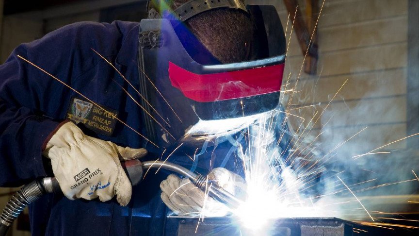
Heavy duty industrial welding positioner in automated fabrication plant
ISO 9001:2015 Certified · Built for Global OEM Performance

Industrial Welding Positioner Systems

Precision-engineered 2-axis tilting turntables, headstock-tailstock systems & robotic positioners (50 kg to 50,000 kg load capacity) designed to maximize arc-on time and weld integrity.

50 T
Max Load Capacity
350%
Arc-On Time Efficiency
22,600+
Global Installations
21+
Years R&D Excellence
Advanced Power Sources Limited · Direct OEM Engineering

Precision-Engineered Industrial Welding Positioner Manufacturing

An Industrial Welding Positioner is the foundation of high-productivity automated welding cells. By manipulating heavy, complex fabrications into optimum flat (1F/1G) downhand welding positions, industrial fabricators dramatically improve arc-on time, deposit up to 400% more weld metal per shift, and eliminate costly crane handling risks.

At APS Welding (Advanced Power Sources Limited), we engineer and manufacture heavy-duty 2-axis tilting welding positioners, headstock-tailstock turntables, and custom servo positioning tables at our ISO 9001:2015 certified production facility in Valsad, Gujarat, India. Unlike trading suppliers who assemble third-party gearboxes onto basic frames, our mechanical and electrical engineering teams design the complete drive mechanism, zero-backlash gearing, structural chassis, and VFD rotation control under one roof.

Whether you are joining high-pressure piping spools, fabricating earthmoving loader arms, assembling wind turbine tower flanges, or welding ASME Section VIII pressure vessels, APS industrial welding positioners provide zero-drift stability, rated rotational torque, and continuous high-current electrical grounding required for severe multi-shift duty cycles.

  • Load capacities ranging from 50 kg benchtop units to 50,000 kg heavy floor tables
  • Dual-axis 360° continuous rotation & 0° to 135° motorized/hydraulic tilting
  • Self-locking double-reduction worm gears with fail-safe electromechanical braking
  • High-capacity copper slip rings (500A to 1200A) preventing bearing arc-pitting
  • Variable Frequency Drive (VFD) stepless rotation speed regulation with LED tachometer
  • Fully compliant with CE Machinery Directives & EN 1090 structural integrity
Inquire Now
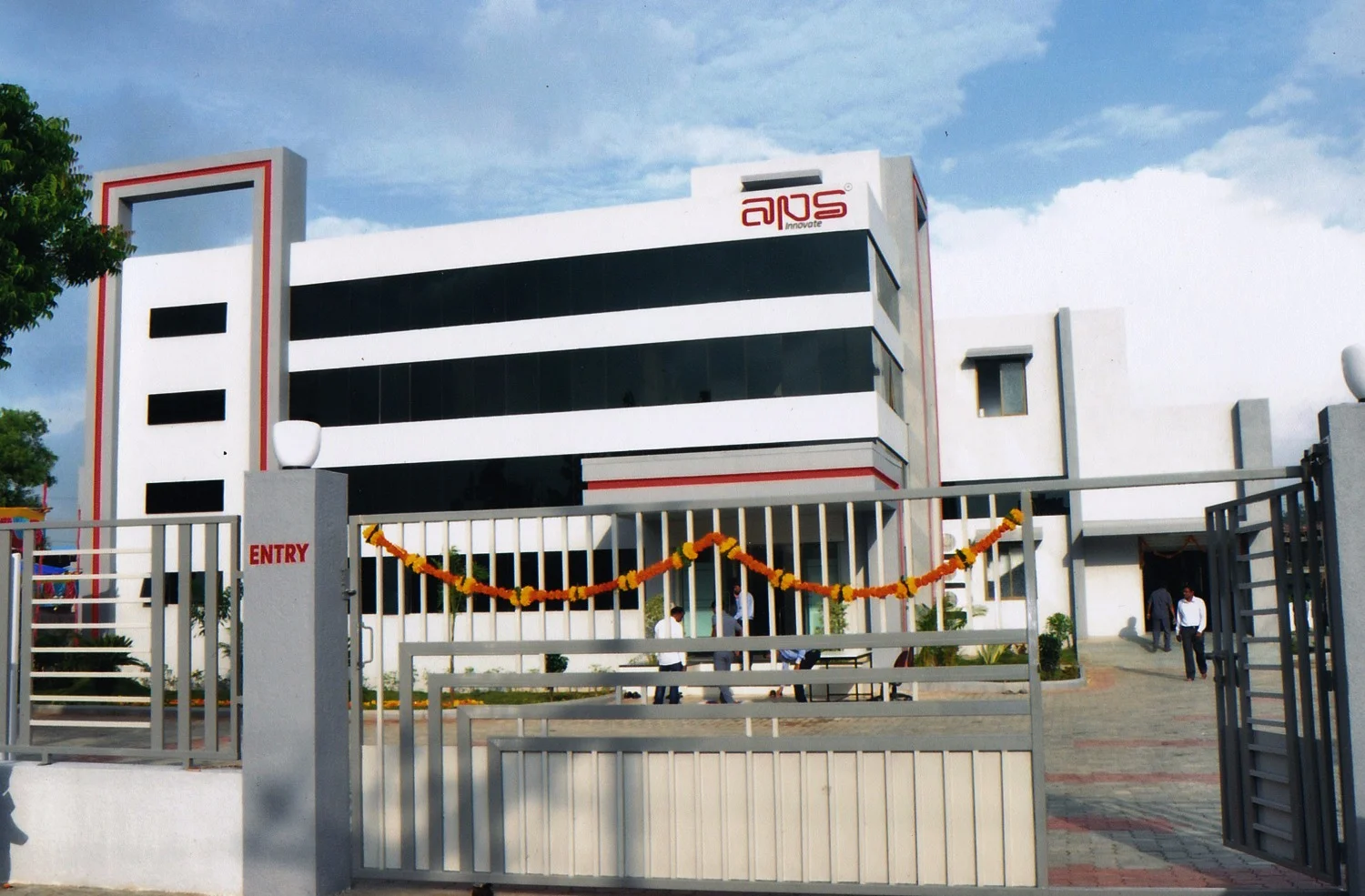
APS Welding manufacturing facility and positioner assembly workshop in Gujarat
ISO 9001:2015 In-House Mechanical & Electrical R&D
Engineering Insights & Selection Science

How to Calculate Load Capacity, Center of Gravity (CG) Offset & Tilting Torque

Procurement failures with industrial welding positioners typically stem from underestimating offset distance and eccentricity torque. A table rated for 5,000 kg will instantly stall or damage its gear teeth if the workpiece center of gravity extends beyond specified limits.

Selection Formula 1

Tilting Torque ($T_t$) Calculation

The tilting motor and gear box must overcome the moment generated by the workpiece weight located at a distance from the tilt axis pin center.

$T_t = W \times (CG_{offset} + H_{table})$

Where:
• $W$ = Total Workpiece Weight + Fixture Weight (kg or N)
• $CG_{offset}$ = Distance from Table Faceplate to Workpiece CG (mm)
• $H_{table}$ = Distance from Tilt Shaft Centerline to Table Faceplate (mm)

If a 3,000 kg vessel head has its Center of Gravity located 400 mm away from the faceplate, and the table offset is 180 mm, the minimum dynamic tilting torque rating required is: $3000 \text{ kg} \times 0.58 \text{ m} = 1740 \text{ kg}\cdot\text{m} \approx 17.07 \text{ kNm}$ (excluding safety margins).

Selection Formula 2

Rotational Torque ($T_r$) & Eccentricity Calculation

Rotational resistance occurs when the center of gravity of an asymmetrical component is offset from the center of table rotation.

$T_r = (W \times e) + T_{friction}$

Where:
• $W$ = Total Workpiece Weight (N)
• $e$ = Eccentricity distance (distance from rotational center to CG axis) (m)
• $T_{friction}$ = Bearing & slip ring frictional drag torque (Nm)

APS positioners incorporate a 1.5x dynamic safety factor on rotational drive worm gears to absorb startup inertia, sudden arc-stop thermal shocks, and accidental off-center clamping loads during heavy structural fabrication.

APS Industrial Positioner Loading & CG Offset Reference Matrix

Positioner Model Max Table Load Rated CG Distance Rated Eccentricity ($e$) Tilting Range Grounding Capacity Primary Industrial Application
WP-300 Light 300 kg 150 mm 100 mm 0° – 90° (Manual / Motor) 500 A Continuous Small Pipe Flanges, Valve Bodies, Elbows
WP-1000 Standard 1,000 kg 300 mm 150 mm 0° – 135° Motorized 800 A Continuous Process Piping Spools, Hydraulic Cylinders
WP-3000 Heavy 3,000 kg 400 mm 200 mm 0° – 135° Motorized Gear 1000 A Continuous Pressure Vessel Heads, Excavator Arm Welds
WP-10000 Titan 10,000 kg 500 mm 300 mm 0° – 120° Hydraulic/Gear 1200 A Continuous Wind Tower Flanges, Large Shell Ring Joints
HST-30000 Dual 30,000 kg Headstock / Tailstock 350 mm Radial 360° Rotational Sync 1200 A Dual Loop Trailer Frames, Transformer Tanks, Structural Beams

* Note: Higher load models (up to 50 Tons) and custom servo-driven robotic integration platforms are built to project specifications. Contact APS engineering for dynamic FEA structural reports.

Product Catalog & Technical Specifications

Industrial Welding Positioner Product Series

Engineered for seamless integration with MIG, TIG, SAW, and Plasma cladding equipment. Choose from four core industrial categories designed for specific shop-floor geometries.

Light to Medium Duty
WP Series (50kg - 1t)

Benchtop & Compact Floor Positioners

Designed for fast setup when welding pipe spools, small pressure fittings, turbine nozzles, and round flanges. Compact footprint with variable speed foot switch control.

  • Rotation DriveAC Inverter VFD Drive
  • Tilt Angle0° to 90° / 135° Manual/Motor
  • Table MachiningRadial T-Slots & Center Bore
  • Ground Conduction500A Brass Slip Ring
Heavy Fabrication
HD-WP Series (2t - 20t)

Heavy Gear-Tilt Workpiece Positioners

Built for structural fabricators handling heavy vessel heads, pump housings, and offshore structures. Features dual-drive tilting segment gears and anti-backlash worm drives.

  • Tilt DriveDouble-Reduction Gear Motor
  • Speed Stability±1% Inverter Controlled
  • Chassis FrameStress-Relieved Heavy Steel
  • Remote ControlHandheld Pendant with Speed Display
Long Weldments
HST Series (Up to 50t)

Synchronized Headstock & Tailstock Systems

Ideal for long linear structures such as trailer chassis, crane booms, utility poles, and heat exchanger frames. Fixed or motorized tailstock riding on floor tracks.

  • SynchronizationDigital Servo / VFD Master-Slave
  • Height AdjustmentMotorized Hydraulic Lift Options
  • Clamping FixturesSelf-Centering 3-Jaw / Custom Arms
  • Safety LockPositive Mechanical Pinning
Robotics & IoT
RWP Servo Series

Robotic 2-Axis Servo Welding Positioners

High-precision 2-axis positioners powered by AC servo motors and planetary gear reducers. Interfaced directly with FANUC, ABB, KUKA, Yaskawa, and APS WeldVisor IoT.

  • Repeatability±0.05 mm Axis Precision
  • Bus InterfacePROFINET, EtherCAT, CANopen
  • Dynamic Backlash< 1 arc-min Precision Reducer
  • Weld TrackingIntegrated Encoder Feedback
Global Manufacturing Dynamics

Industry Development Trends Shaping Welding Automation

01

India as a High-Value Manufacturing Hub

Global procurement teams are shifting heavy equipment sourcing from traditional high-cost markets toward India. Advanced manufacturers like APS deliver European-grade mechanical tolerances and heavy steel construction at optimal capital expenditure ratios.

02

Strict Quality Code Compliance

Welding codes (ASME Section VIII, ISO 3834, EN 1090) now scrutinize positional welding. Positioners ensure every pass occurs in the 1F/1G flat position, guaranteeing deeper penetration, zero undercut, and complete radiographic inspection compliance.

03

Ergonomic Safety & Zero-Harming Workspaces

Occupational safety regulations (OSHA / CE) prohibit manual turning of heavy weldments via overhead cranes. Automated tilt-turn tables reduce crane utilization by up to 80%, eliminating crane-swing hazards and operator strain injuries.

04

Modular Customization for Complex Profiles

Off-the-shelf positioners are giving way to modular architectures. APS custom-fits hydraulic height adjustment pins, hollow spindle bores for purge gas delivery, and specialized pneumatic chucking jaws tailored to complex geometry fabrications.

Field-Tested Applications

Proven Performance Across Critical Industries

From nuclear pressure vessel fabrication to cross-country pipeline spools, see how APS industrial positioners perform under demanding operational conditions.

Pressure Vessels & Boiler Shells

A leading boiler manufacturer integrated an APS 15-Ton Heavy Duty Positioner with an APS Endeavour 1250 Submerged Arc Welder. Result: Circumferential seam welding time reduced by 62% with zero defect rates under X-ray inspection.

Oil & Gas Piping Spool Fabrication

Deploying APS 3-Ton Positioners with hollow spindle gas purge channels allowed a Middle East pipe contractor to achieve continuous TIG root passes and MIG cap fills on stainless steel pipes with continuous 1000A grounding protection.

Heavy Earthmoving Machinery

An OEM of excavator booms utilized APS Robotic 2-Axis Servo Positioners synchronized with 6-axis welding robots, achieving 0.05 mm repeatability and doubling daily chassis throughput.

Procurement Best Practices

5-Point Verification Checklist for Global Buyers

Avoid common procurement missteps. Verify these critical parameters with your engineering team before submitting your RFQ for an industrial welding positioner.

Inquire Now
  1. Calculate Center of Gravity (CG) Offset

    Provide exact dimensional drawings showing the distance from the table surface to the workpiece center of mass. Do not rely solely on gross weight.

  2. Specify Maximum Welding Amperage & Duty Cycle

    Ensure the positioner ground slip ring matches your maximum output. High-amperage SAW welding (800A–1200A) requires dual-brush carbon copper ground assemblies.

  3. Determine Speed Regulation & Surface Travel Rate

    Verify that the motor VFD offers a wide turndown ratio (e.g., 0.05 to 1.5 RPM) to maintain uniform linear surface weld speeds across small and large radii.

  4. Confirm Input Power & Environmental Factors

    Specify local power requirements (e.g., 380V/415V/480V at 50/60 Hz) and environmental conditions (hot, humid, dust-filled workshop environments).

  5. Audit Mechanical Safety Mechanisms

    Check for double-worm self-locking reducers, physical limit switches on tilt axes, emergency stop circuits, and heavy structural anchor plates.

Frequently Asked Questions

Industrial Welding Positioner FAQ

Answers to critical questions asked by global procurement managers, welding engineers, and plant automation specialists.

How do I calculate the required load and torque capacity for an industrial welding positioner?

To size an industrial welding positioner accurately, you must consider both total workpiece weight and Center of Gravity (CG) offsets. Tilting torque ($T_t$) is calculated as $T_t = \text{Workpiece Weight} \times (\text{CG Distance} + \text{Table Top Distance})$. Rotation torque ($T_r$) is calculated as $T_r = (\text{Workpiece Weight} \times \text{Eccentricity Distance}) + \text{Frictional Resistance}$. APS application engineers assist global buyers by evaluating 3D CAD models to calculate dynamic moment vectors before recommending a specific model.

What safety mechanisms prevent table drift or backlash on heavy tilting positioners?

APS industrial welding positioners utilize self-locking double-reduction worm gearboxes combined with heavy-duty electromagnetic fail-safe motor brakes. This dual-redundant mechanical design prevents gravitational table creep or backlash when holding asymmetrical heavy structures at maximum tilt angles (up to 135°), even during total plant electrical power failure.

Can APS welding positioners integrate with robotic arms and automatic welding tractors?

Yes. APS positioners can be specified with absolute servo encoders, digital VFD controllers, and industrial fieldbus interfaces (CANopen, PROFINET, Modbus TCP). This allows zero-latency synchronization with robotic welding arms (FANUC, ABB, KUKA, Yaskawa) and automatic column-and-boom SAW or MIG welding manipulators.

How does welding current grounding work on high-amperage positioning tables?

APS welding positioners feature dedicated heavy-duty copper-alloy grounding slip rings rated from 500A to 1200A continuous duty. This direct-conduction grounding bypasses drive shafts, bearings, and gearboxes, completely eliminating electrical arc pitting and premature bearing failure during high-amperage SAW, MIG, or TIG operations.

What are the primary differences between 2-axis tilt-turn positioners and headstock-tailstock systems?

Standard 2-axis tilt-turn positioners rotate 360 degrees and tilt up to 135 degrees, making them ideal for compact, symmetrical workpieces like flanges, pipe spools, valves, and vessel heads. Headstock-tailstock positioners suspend long, linear components (such as structural beams, trailer chassis, or long tanks) horizontally between two synchronized rotating chucks, accommodating high bending moments without requiring extreme ceiling clearance.

What export power configurations and safety certifications does APS provide for global procurement?

APS exports industrial welding positioners configured for international plant voltages including 380V, 415V, 460V, and 480V at 50 Hz or 60 Hz (3-phase). All positioning systems adhere to ISO 9001:2015 quality manufacturing, CE machinery directives, and international electrical safety standards IEC 60204-1.

Optimize Your Welding Automation Cell Today

Send your workpiece dimensions, CG data, and welding process requirements to our senior application engineering team.

Inquire Now