
[email protected] Sales: +91 96014 44111 Service: +91 96013 33888
0%

Choosing a Cold Wire Feeder for TIG Welding requires more than matching a machine to a torch. The feeder must suit the alloy, joint design, wire diameter, and production rhythm. A unit that performs well on stainless steel may struggle with thin aluminum. Small differences matter. Wire feeding should remain steady beside the tungsten arc, even during slow travel speeds.

Dr. John C. Lippold, a respected welding metallurgist and author, states, “Weld quality begins with understanding the material, the process, and the application.” That principle should guide every purchase. Examine the feeder’s drive-roll design, motor control, wire tension, and synchronization options. Confirm whether it supports the required wire sizes. Check its compatibility with the TIG power source and torch system. A smooth feeder should deliver wire without buckling, vibration, or sudden surges.

Look closely at real workshop conditions. Will the equipment face dust, heat, long cables, or frequent setup changes? A compact feeder may help on maintenance work, while a programmable model may better serve repeatable fabrication. Ask for practical demonstrations using your actual filler wire. Catalog claims can look impressive. They do not replace a weld test.

There is room for judgment. The most expensive feeder is not always the best choice. An overlooked control may create more trouble than a missing feature. Review operator feedback, service availability, spare parts, and warranty terms before deciding. Reliable feeding supports cleaner starts, consistent deposition, and fewer interruptions. Still, no feeder can correct poor joint preparation or careless parameter selection. The machine helps. The welder remains responsible.
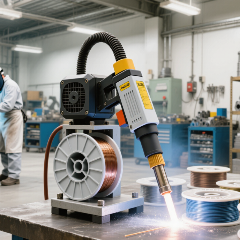
How to Choose a Cold Wire Feeder for TIG Welding?

What a Cold Wire Feeder Does in TIG Welding

In TIG welding, a cold wire feeder supplies filler metal without heating it before delivery. The wire enters the weld pool near the tungsten arc. This makes filler placement more consistent, especially during long welds or repeated joints. The feeder usually includes a spool, drive rollers, guide liner, motor, and speed controller. Some systems also coordinate wire movement with welding current.

The operator sets wire speed, direction, and feeding timing. A steady feed can produce a smoother bead and reduce hand fatigue. It is useful for stainless steel seams, aluminum fabrication, and controlled root passes. Watch the wire path carefully. A sharp bend can increase resistance and cause uneven feeding. The wire should meet the molten pool gently, not strike the tungsten electrode.

Cold wire feeding also changes how the welder manages heat. More filler can support a larger pool, but excessive wire may cool the joint or create poor fusion. I have seen operators increase wire speed when the real problem was low travel speed. That assumption is not always correct. Selection should match wire diameter, material, torch access, and required deposition rate. Check whether the feeder offers fine speed adjustment and reliable tension control. Test it on scrap metal first. Small changes in wire angle can noticeably alter bead shape.

How to Choose a Cold Wire Feeder for TIG Welding?

What a Cold Wire Feeder Does in TIG Welding

A cold wire feeder delivers unpowered filler wire into the TIG weld pool while the welding torch supplies the arc heat. The chart compares common filler wire diameters by cross-sectional area, calculated as π × diameter² ÷ 4. Smaller diameters are useful for precise, lower-deposition work, while larger diameters require more melting capacity and are suitable for higher deposition rates. Actual wire-feed speed should be selected according to material, joint design, welding current, travel speed, and the required filler addition.

How to Match Wire Feeder Types to TIG Welding Applications

How to Choose a Cold Wire Feeder for TIG Welding?

Matching a cold wire feeder to the TIG application starts with the joint, not the machine. A compact push feeder suits short welds, small wire diameters, and accessible joints. It works well on stainless steel tubing, thin sheet, and controlled workshop repairs. Keep the spool close to the torch. Long liner paths can increase drag and cause uneven feeding.

For larger structures, a push-pull feeder offers better control through longer cables. The pushing motor supplies wire, while the pulling motor stabilizes movement near the torch. This arrangement suits aluminum, where soft wire can buckle inside a liner. It also helps during continuous welding on frames, tanks, and wide seams. For narrow gaps, choose a programmable feeder with low-speed starting and adjustable pulse delivery. These settings reduce wire impact and help maintain a clean molten pool.

Wire size matters more than many operators expect. A feeder designed for 0.8 mm wire may struggle with 1.2 mm wire, especially around tight bends. Check the liner, drive rolls, torch connection, and motor torque together. I have seen excellent TIG settings fail because the feeder was treated as an accessory. That was a costly assumption. A perfect specification can still perform poorly after dust enters the liner or the spool tension is set too high. Test the actual wire, travel position, and welding angle before production. Small adjustments reveal problems early.

Which Technical Specifications Should You Compare?

Choosing a cold wire feeder for TIG welding starts with technical specifications, not casing design.

The American Welding Society’s 2023 workforce report forecasts a U.S. shortage of 330,000 welding professionals by 2028. That pressure makes repeatable feeding increasingly important.

Compare compatible wire diameters first. A feeder for 0.8–1.2 mm wire may not suit fine aluminum or nickel work. Check feed-speed range, speed resolution, and actual delivery accuracy. A wide range is useful, but unstable low-speed feeding can ruin a small fillet.

Ask for test data, not only “high precision” claims. I would measure wire movement over several minutes.

Motor torque and control response also matter. A rigid four-roll system can reduce slipping, especially with soft aluminum wire. However, extra rollers may increase maintenance. The feeder should synchronize with TIG current, travel speed, and arc start signals.

ISO 4063 identifies TIG as process 141, but it does not define feeder performance. Buyers must compare those details separately.

Check duty cycle, spool capacity, wire-path material, and enclosure rating. A compact spool saves space. It may also require more frequent changes.

The International Welding Institute’s technical guidance repeatedly stresses process stability and controlled consumables. Still, published figures can be difficult to compare because test methods differ.

In practice, record feeding accuracy, response delay, and downtime during a real weld trial. That evidence is often more useful than a polished specification sheet.

How to Select Compatible Wire, Torch, and Power Supply Components

Choosing a cold wire feeder for TIG welding starts with compatibility, not feeding speed. The feeder must match the wire diameter, material, and required feed range. Check the drive rolls, liner, and guide tube before ordering. A soft aluminum wire needs gentle, correctly sized rolls. Stainless or harder wire may require different contact surfaces. Measure the spool space too. A feeder that fits the wire can still overload the mounting area.

The torch connection deserves equal attention. Confirm the torch lead, trigger circuit, shielding gas path, and feeder control signal. Some setups use a separate control cable, while others rely on an integrated connection. Never assume the plug shape proves compatibility. Verify pin functions with the equipment manuals and a qualified technician. Keep the wire entry close to the arc. A long, unsupported path can cause loops, drag, and uneven deposition.

Power supply matching affects arc stability. Check rated output, duty cycle, polarity, and remote-control requirements. The feeder should not draw more auxiliary power than the supply can provide. Test the system at low wire speed before production welding. Watch the first few centimeters of wire entering the puddle. I once focused on torch fit and missed a control-voltage mismatch. The feeder ran, but adjustment was unreliable. That mistake reinforced a useful habit: record every connector, rating, and setting before purchase. A written checklist feels slow, yet it prevents expensive trial and error.

How to Install, Adjust, and Test a Cold Wire Feeder

Choosing a cold wire feeder for TIG welding begins with compatibility. Check the feeder’s wire diameter range, control signal, mounting space, and torch connection. The unit should match your TIG power source and support the filler wire used for the joint.

Turn off and isolate the welding equipment before installation. Secure the feeder on a stable surface, then connect the control cable and welding ground correctly. Install the correct drive rolls and guide liner for the wire diameter. Thread the wire gently through the inlet, liner, and torch guide. Keep the spool aligned with the feed path. Excessive tension can deform soft wire.

Small details matter.

Set the drive pressure until the wire moves smoothly without slipping or flattening. Begin with a low wire speed, then increase it during a dry-feed test. Watch the wire exit from the torch. It should travel straight and steadily, without sudden jumps. I once used excessive pressure during setup, and the wire became visibly marked. That mistake reminded me to inspect the wire path, not only the motor.

Test the feeder without an arc first. Confirm forward and reverse controls, wire cutoff, and emergency stopping functions. During a controlled weld test, use clean base metal and observe puddle size, wire entry angle, and feeding consistency. Adjust wire speed in small steps. If the wire touches the tungsten, stop and correct the torch angle or feeder alignment. Record the final settings, although real joints may still require careful adjustment.

How to Choose a Cold Wire Feeder for TIG Welding? - How to Install, Adjust, and Test a Cold Wire Feeder

Category Selection or Setup Dimension Practical Data or Recommended Range Why It Matters / Verification Method
Welding Process TIG compatibility Use a feeder specifically designed for cold-wire TIG operation and synchronized with the welding power source. The feeder must add wire without disturbing arc start, crater fill, pulse timing, or shielding-gas control.
Wire Diameter Supported filler wire size Common TIG filler sizes are approximately 0.8, 1.0, 1.2, 1.6, 2.0, and 2.4 mm. Select a feeder and guide set that match the required diameter. Incorrect guides or drive rolls can cause wire slipping, buckling, surface damage, or inconsistent deposition.
Wire Material Material compatibility The wire path should be suitable for stainless steel, carbon steel, aluminum, nickel alloys, or other specified filler materials. Soft aluminum wire requires a low-friction, well-supported path and correctly matched drive-roll pressure.
Feed Rate Adjustable wire-feed speed A useful planning range is about 0.2–8.0 m/min, although the actual range depends on the feeder, wire diameter, welding current, and joint design. Start at a low rate and increase gradually until the bead has adequate reinforcement without cold-lap or excessive buildup.
Welding Current Power-source operating range Choose a feeder that can operate with the intended TIG power source, commonly from approximately 5–350 A for general fabrication equipment. Confirm connector type, control signal, duty cycle, and current limits in the equipment documentation before installation.
Control Method Manual, remote, or synchronized control Select independent speed control for manual work, or trigger/pulse synchronization for automated and repeatable welding. Synchronization helps coordinate wire movement with arc current and reduces variation between welds.
Installation Position Feeder placement Place the feeder on a stable surface, close enough to minimize the wire-path length, while keeping it away from welding spatter, heat, and moisture. A short, straight wire path reduces drag and improves feeding stability.
Mechanical Installation Drive rolls, guides, and liner Install the correct drive-roll groove, inlet guide, outlet guide, and liner for the selected wire diameter and material. The wire should pass smoothly by hand with no sharp bends, excessive resistance, or visible flattening.
Electrical Connection Power and control cables Disconnect power before connecting. Secure the feeder power supply, trigger/control cable, and any synchronization connection. Loose or incompatible connections may cause intermittent feeding, false starts, or equipment damage.
Torch Alignment Wire-entry angle and position Align the wire guide with the weld-pool feeding direction. Keep the wire path as straight as practical and avoid contact with the tungsten electrode. Poor alignment can deflect the wire, contaminate the tungsten, and produce uneven bead placement.
Drive-Roll Pressure Pressure adjustment Set the lowest pressure that feeds the wire reliably. Do not use excessive pressure to compensate for a blocked liner or misaligned guide. Excessive pressure can deform soft wire and increase feeding resistance; insufficient pressure causes slipping.
Initial Feed Setup Starting wire-feed rate Begin around 20–30% of the feeder's available speed range, then increase in small steps during a test weld. A gradual adjustment makes it easier to identify whether the problem is feed rate, torch position, current, or shielding gas.
Shielding Gas Gas type and flow Use the gas specified for the base and filler materials. A common TIG flow range is approximately 8–15 L/min, subject to nozzle size and working conditions. Too little gas can cause porosity and oxidation; excessive flow can create turbulence and draw air into the shielding zone.
Dry-Run Test Wire movement without arc Activate the feeder without welding and observe the wire for at least 30 seconds at low, medium, and intended operating speeds. Check for pulsing, slipping, bird-nesting, abnormal noise, or inconsistent wire extension.
Arc Test Test coupon and bead appearance Use the same base material, filler diameter, joint type, current, travel speed, and shielding gas planned for production. A stable arc and smooth, uniform bead indicate that the feeder and welding parameters are working together.
Wire Placement Addition point and timing Feed the wire into the leading edge or front portion of the weld pool without touching the tungsten electrode. Correct placement reduces tungsten contamination, undercut, lack of fusion, and irregular reinforcement.
Acceptance Check Visual and dimensional inspection Check bead width, reinforcement, fusion at both toes, surface oxidation, porosity, spatter, and crater shape. Record the successful current, travel speed, wire-feed rate, gas flow, torch angle, and wire position for repeatability.
Maintenance Routine service Inspect guides, liner, drive rolls, wire reel tension, connectors, and cooling or ventilation openings before regular use. Replace worn guides and contaminated liners; clean the wire path to prevent drag and unstable feeding.
Technical note: The numerical ranges shown are general planning values. Always verify the feeder's actual wire-size, speed, duty-cycle, power, control-interface, and material requirements before purchase or installation.

FAQS

Which wire diameters should I compare before choosing a cold wire feeder?

Check the feeder’s supported range first. A unit handling 0.8–1.2 mm wire may not suit fine aluminum or nickel work. Compatibility matters more than appearance.

Why is low-speed feeding accuracy important?

A small fillet can fail when the wire jumps at low speed. Test wire movement for several minutes. “High precision” alone proves little.

What motor and roller features should I examine?

Check motor torque, control response, and roller design. Four rollers can reduce slipping with soft aluminum wire. More rollers may also increase maintenance.

How should the feeder synchronize with the TIG process?

Confirm compatibility with current, travel speed, and arc-start signals. A process code does not guarantee feeder performance. Compare these controls separately.

What installation checks prevent wire damage?

Turn off and isolate the welding equipment. Install matching drive rolls and a suitable liner. Keep the spool aligned. Too much pressure can flatten soft wire.

How can I adjust drive pressure correctly?

Start with low pressure. Increase it until the wire moves smoothly without slipping. Inspect the wire for marks. I once used excessive pressure and missed this simple warning.

What should I test before creating an arc?

Run a dry-feed test first. Check forward and reverse movement, cutoff, and emergency stopping. Watch the wire exit. It should move straight, not jump.

What should I observe during a controlled weld trial?

Use clean base metal and watch puddle size, entry angle, and feeding consistency. Change speed in small steps. If the wire touches the tungsten, stop immediately.

Which performance records are useful after testing?

Record feeding accuracy, response delay, final settings, and downtime. Real joints may still need adjustment. Published figures can be hard to compare, unfortunately.

Conclusion

Choosing the right Cold Wire Feeder for TIG Welding can improve deposition control, productivity, and weld consistency without compromising the precision of the TIG process. A cold wire feeder delivers filler wire into the weld pool at a controlled rate, helping operators manage joint filling, heat input, and bead shape. The best feeder type depends on the application, including material, wire diameter, welding position, joint design, and whether manual, semi-automatic, or automated operation is required.

When comparing options, consider wire feed speed range, motor control, feeding stability, spool capacity, adjustment accuracy, and compatibility with the welding current and control signals. The feeder, torch, wire guide, liner, and power supply should work together as a complete system. Before welding, install the components carefully, align the wire path, set the feed direction and speed, and confirm that the filler wire enters the leading edge of the molten pool smoothly. A short test weld can help verify arc stability, wire delivery, bead appearance, and overall system performance.

Clara

Clara

Clara is a professional marketing specialist who combines a strong understanding of the company’s products with a clear, customer-focused approach to communication. She regularly contributes expert articles to the company website, helping readers understand product features, practical applications,......