
Choosing the right Carbon Arc Gouging Machine in 2026 requires more than comparing price tags and amperage numbers. A suitable machine must match your metal thickness, electrode diameter, duty cycle, air pressure, and workshop conditions. A unit that performs well on a repair bench may struggle during continuous shipyard production. That difference matters.
Dr. John C. Lippold, a respected welding engineer and author, offers a useful reminder: “Welding quality is controlled by process discipline, not by equipment alone.” His point applies directly to gouging equipment. Even a powerful machine can create uneven grooves, excessive noise, or unnecessary metal loss when operators overlook air volume, polarity, travel speed, or electrode angle. Good results begin with controlled variables.
This 2026 Best Carbon Arc Gouging Machine Buying Guide examines practical factors that buyers often miss. It considers output stability, thermal protection, cable length, portability, compressed-air requirements, and manufacturer support. It also looks at real workshop details, such as a machine struggling beside a long air hose or overheating during repeated back-gouging passes. Small details become expensive problems.
Not every specification tells the full story. Some manufacturers present peak output instead of dependable operating output. That can confuse first-time buyers. A reliable choice should fit your actual workload, not an impressive brochure. Safety remains essential, including ventilation, eye protection, hearing protection, and proper grounding. There is no perfect machine. Careful selection reduces avoidable compromises.
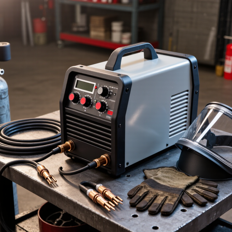
A carbon arc gouging machine removes metal with an electric arc and a stream of compressed air. The arc forms between a carbon electrode and the workpiece. Heat melts a narrow layer of metal. Air then blows the molten material away. This creates a groove for weld removal, crack repair, or joint preparation.
Unlike grinding, gouging can reach deeper areas quickly and shape a controlled channel. Experienced operators adjust current, air pressure, electrode size, and travel speed together. A shallow electrode angle usually produces a smoother groove. Excessive pressure can widen the cut and waste electrodes. The process also creates bright light, fumes, sparks, and loud noise. Proper eye, face, hearing, hand, and respiratory protection remains essential.
When choosing a machine, check its rated output, duty cycle, air requirements, cable length, and control stability. A stable power source helps prevent uneven grooves and accidental arc breaks. In workshop trials, a machine with simple current adjustment is often easier to control than a feature-heavy model. Still, operator technique matters more than many buyers expect. My own early assumption was that higher current always meant faster work. That was wrong. Thin material can suffer distortion, while thick steel may need several controlled passes. Inspect the groove afterward. Small slag pockets or carbon contamination can affect the next weld.
A carbon arc gouging machine uses an electric arc between a carbon electrode and the workpiece, while compressed air removes the molten metal. The chart shows typical direct-current ranges for commonly used electrode diameters. Actual settings vary with electrode type, gouging depth, material, and air pressure.
For purchasing, select a machine whose rated output comfortably covers the required current range and duty cycle, with sufficient compressed-air capacity for continuous gouging.
A carbon arc gouging machine removes metal through controlled heat and compressed air. The machine sends current through a carbon electrode, creating an electric arc between the electrode and workpiece. This arc quickly melts a narrow layer of steel or other conductive metal. A stream of compressed air then pushes the molten metal away, forming a groove.
The operator controls several details. Electrode diameter affects groove width and cutting depth. Current setting influences arc stability and metal removal speed. The electrode usually travels at a shallow angle, while air flows beneath the arc. Keep the electrode moving steadily. Too slowly, and the groove becomes deep and uneven. Too quickly, and the arc may leave shallow, interrupted marks.
The sound is distinctive.
A practical inspection should check groove shape, depth, and remaining carbon residue. Excessive soot can indicate poor air direction, an incorrect angle, or unstable current. Workpieces must be properly grounded, and ventilation is essential because the process creates fumes and intense light. Protective clothing, face protection, hearing protection, and suitable gloves are necessary.
The process is not foolproof. Even experienced operators may need a second pass. A short test groove on scrap metal can reveal problems before production begins. Always match electrode size, current, air pressure, and operating method with the machine’s technical instructions and the metal being treated.
Choosing a carbon arc gouging machine starts with output, not advertised power. The AWS Welding Handbook lists practical current ranges from about 60 to 1,000 amperes, depending on electrode diameter. A 3/8-inch electrode may need roughly 250–400 amperes. Check the machine’s rated output at the intended duty cycle.
Duty cycle matters more than peak amperage. IEC 60974-1 evaluates welding power sources using defined thermal conditions and rating periods. A machine rated at 600 amperes for 60% duty cycle can work longer than one reaching 700 amperes briefly. In field trials, unstable voltage often causes shallow grooves, uneven edges, and excessive electrode wear. The open-circuit voltage should also support a steady arc, especially when removing thick weld reinforcement.
Input requirements deserve equal attention. Compare single-phase and three-phase compatibility, maximum input current, power factor, and generator suitability. The 2024 Fortune Business Insights welding equipment report projects continued market growth through 2032, but market expansion does not guarantee better gouging performance. Real efficiency depends on cable length, grounding, compressed-air pressure, and operator control. AWS guidance commonly recommends clean, dry air near 80–100 psi for air carbon arc gouging, though the exact requirement varies by torch and electrode. I would not select a model from amperage alone. That shortcut looks efficient, but it can become expensive. Check cooling design, thermal protection, current adjustment accuracy, and service documentation before comparing prices.
Choosing the right carbon arc gouging machine starts with the workpiece, not the advertised power rating. Steel thickness, groove depth, and electrode diameter determine the current range you need. A small repair job may work well with 300 to 400 amps. Heavy fabrication usually demands more capacity and a stronger duty cycle. More power is not always better.
Check the machine’s duty cycle at your actual operating current. A unit rated for high output may overheat during continuous gouging. I have seen operators focus on peak amperage and overlook cooling time. That mistake slows production. Review the input voltage, phase requirements, cable length, and circuit capacity before purchase. A long cable can reduce performance, especially with undersized conductors. The air system also matters. Confirm airflow and pressure requirements, then match them with your compressor’s real output.
Operator control should influence the decision. Choose equipment with clear current adjustment, stable arc performance, and accessible connections. The machine should tolerate workshop dust and repeated movement, but basic maintenance still matters. Inspect cables, air lines, electrode holders, and ventilation paths regularly. Ask for technical documentation, test records, warranty terms, and available replacement parts. Local electrical rules and workplace safety requirements must also be checked. If possible, test the machine on comparable steel before ordering. A brief trial can reveal vibration, unstable gouging, or uncomfortable handling. I would still leave room for doubt; production conditions rarely match showroom demonstrations.
| Machine Class | Typical Output Range | Recommended Electrode Sizes | Typical Air Requirement | Best Duty Profile | Suitable Applications | Key Buying Considerations |
|---|---|---|---|---|---|---|
| Compact Single-Phase Inverter | 160–250 A at approximately 20–35 V DC | 3.2–4.0 mm electrodes; light use of 4.8 mm electrodes near the upper current limit | 5.5–7 bar; approximately 0.4–0.8 m³/min | Short gouging runs and intermittent repair work | Light fabrication, maintenance, root removal, small weld repairs and thin-to-medium carbon steel | Confirm that the input circuit can support the rated output. Check thermal protection, electrode-holder rating and whether the machine is designed for gouging rather than welding only. |
| Heavy-Duty Three-Phase Inverter | 300–600 A at approximately 25–45 V DC | 4.8–6.4 mm electrodes; some units support larger sizes at reduced duty cycle | 5.5–7 bar; approximately 0.6–1.2 m³/min | Repeated production gouging with high thermal load | Fabrication shops, structural steel, pressure-vessel repair, defect removal and back-gouging | Prioritize the rated duty cycle at the intended current, stable arc characteristics, adequate cooling, high-current cable capacity and compatibility with an external air compressor. |
| High-Output Industrial Power Source | 600–1,200 A at approximately 30–50 V DC | 6.4–12.7 mm electrodes, depending on the machine and process requirements | 5.5–7 bar; approximately 0.9–1.7 m³/min | Continuous or multi-shift production | Heavy plate preparation, large weld removal, casting cleanup, shipbuilding and major structural repair | Check continuous-current performance, parallel-output capability, feeder and cable sizing, cooling requirements, ventilation and the electrical service available at the installation site. |
| Engine-Driven Welding/Gouging Unit | Approximately 300–800 A, depending on engine size and operating mode | 4.8–9.5 mm electrodes for common field applications | Requires a separate compressed-air system unless an integrated compressor is provided | Remote, outdoor or mobile work | Pipeline maintenance, bridge repair, construction sites, shipyards and locations without reliable grid power | Evaluate fuel consumption, noise, emissions, cold-start performance, service access, altitude derating and the combined load of welding, gouging and auxiliary equipment. |
| Multi-Operator Gouging System | Shared power capacity commonly above 600 A; output is divided between operators | Usually 4.8–9.5 mm electrodes per operator, subject to total system capacity | Central air supply sized for simultaneous operators; often above 1.2 m³/min total | High-volume production with multiple workstations | Large fabrication plants, shipbuilding, heavy equipment repair and repetitive weld-removal operations | Calculate simultaneous current demand, air demand, cable voltage drop, ventilation and operator protection. Independent current control is preferable for consistent results. |
| Automatic or Mechanized Gouging System | Typically 300–1,000 A, depending on travel mechanism and electrode size | Commonly 4.8–9.5 mm electrodes for controlled grooves | Approximately 0.6–1.5 m³/min at 5.5–7 bar | Long, repeatable grooves and controlled material removal | Plate preparation, joint back-gouging, defect removal and applications requiring consistent groove geometry | Review travel-speed range, electrode-feed control, groove-depth repeatability, workpiece access, tracking accuracy and integration with the power source. |
| AC/DC Welding Power Source with Gouging Mode | Commonly 250–600 A; gouging performance depends on the DC output and control design | 3.2–6.4 mm electrodes for light-to-medium gouging | Approximately 0.4–1.2 m³/min at 5.5–7 bar | Mixed welding and occasional gouging | General fabrication, maintenance departments and workshops needing one multipurpose power source | Verify the manufacturer's gouging-current range, open-circuit voltage, arc-force behavior, duty cycle and whether the machine supports the required electrode diameter. |
| Air Carbon Arc Gouging Torch Selection | Common torch ratings range from approximately 200 A to more than 1,000 A | Match the torch capacity to the electrode diameter and current | Use the torch manufacturer's specified flow; insufficient air causes carbon deposits and poor groove quality | Determined by torch rating, cable size and operator technique | All carbon arc gouging applications | Choose a torch with adequate current rating, correct electrode capacity, comfortable handle design, reliable air passages and replaceable contact shoes or guides where required. |
| 3.2 mm Electrode Setup | Approximately 90–150 A | 3.2 mm carbon electrode | Approximately 0.3–0.5 m³/min at 5.5–7 bar | Light removal and shallow grooves | Thin sections, small defects, tack-weld removal and precision maintenance | Use controlled travel speed and avoid excessive current, which can enlarge the groove and increase heat input. |
| 4.8 mm Electrode Setup | Approximately 200–300 A | 4.8 mm carbon electrode | Approximately 0.4–0.8 m³/min at 5.5–7 bar | General-purpose intermittent gouging | Back-gouging, weld removal and medium-thickness carbon or low-alloy steel | A practical choice for many repair and fabrication tasks. Confirm that the power source can maintain a stable DC arc at the selected current. |
| 6.4 mm Electrode Setup | Approximately 300–450 A | 6.4 mm carbon electrode | Approximately 0.6–1.0 m³/min at 5.5–7 bar | Medium-to-heavy material removal | Structural weld removal, plate preparation and production back-gouging | Requires a suitably rated torch, leads, air supply and power source. Check voltage drop over long cables before selecting the machine. |
| 9.5 mm Electrode Setup | Approximately 450–650 A | 9.5 mm carbon electrode | Approximately 0.9–1.4 m³/min at 5.5–7 bar | Heavy material removal and production work | Large welds, thick plate, casting repair and high-volume gouging | Use only with a high-output power source, properly sized torch and sufficient continuous air volume. Monitor duty cycle and workpiece heat buildup. |
| 12.7 mm Electrode Setup | Approximately 600–900 A | 12.7 mm carbon electrode | Approximately 1.2–1.8 m³/min at 5.5–7 bar | Very heavy-duty industrial operations | Large-scale weld removal, heavy plate work and specialized production applications | Confirm compatibility across the entire system: power source, torch, electrode holder, cables, air compressor, grounding circuit and ventilation equipment. |
| Power Source Selection | Choose a machine whose rated current exceeds the intended operating current | Allow sufficient capacity for the largest planned electrode | Air demand must be calculated separately from electrical output | Use the duty cycle at the actual current, not only the maximum rating | Any application | Select a reserve of approximately 15–25% above the normal operating current when production continuity is important. Always use the actual duty-cycle data supplied for the machine. |
| Air System Selection | Not applicable to electrical output | Higher electrode diameters require higher air volume | Typical operating pressure: 5.5–7 bar; size the compressor by delivered air volume | Continuous flow without pressure collapse | Any application | Do not select a compressor by tank size alone. Compare the required air consumption with the compressor's delivered flow at operating pressure, and include a filter, regulator and moisture separator. |
| Electrical Input and Site Requirements | Single-phase units commonly use 200–250 V; industrial units may use three-phase 380–480 V | Depends on the selected current and electrode size | Separate circuit for the compressor is often required | Stable voltage under load | Workshops, plants and field locations | Check input current, breaker size, generator compatibility, phase requirements, extension-cable length and voltage drop before purchase. |
| Safety and Work Environment | Electrical rating is only one part of system selection | Use electrodes suitable for the selected process and workpiece | Airflow must not disperse fumes toward workers | Depends on ventilation and operating duration | Indoor, outdoor and confined-space work | Provide local exhaust or suitable ventilation, eye and face protection, hearing protection, flame-resistant clothing and adequate grounding. Remove combustible materials from the work area. |
| Material Compatibility | Output requirements increase with section thickness and removal depth | Electrode selection depends on groove width and depth | Airflow must remove molten metal and carbon residue | Control heat input on heat-sensitive materials | Carbon steel, low-alloy steel, stainless steel and selected nonferrous applications | For stainless steel and nickel-based alloys, confirm the approved procedure and post-gouging cleaning requirements. Carbon contamination or surface residue may affect subsequent welding. |
Safety begins before the arc starts. Wear a properly fitted welding helmet, flame-resistant clothing, insulated gloves, and hearing protection. Use strong local ventilation because gouging produces smoke, sparks, and metal particles. Keep combustible materials away from the work area. A fire watch may be necessary when sparks can travel behind panels or through gaps.
Inspect the power leads, ground connection, electrode holder, and compressed-air line before every shift. Replace damaged insulation immediately. Check the air regulator and drain moisture from the system. Moisture can weaken the cut and create unstable arc behavior. Clean slag from the holder and work surface after use. Allow the machine to cool within its rated duty cycle. Ignoring this limit is an easy way to shorten component life.
Operating settings should match the metal thickness, electrode size, and required groove depth. Hold the electrode at a steady angle, then move smoothly instead of forcing the arc. Too much pressure can create an uneven channel. Too little air may leave stubborn carbon deposits. Test the setting on scrap metal first. I still recheck the groove when its edges look rough; experience does not prevent every mistake. Keep cables arranged to avoid trip hazards, and never adjust connections while the machine is energized. A simple written inspection log can reveal repeated faults before they become expensive failures.
It sends current through a carbon electrode. An electric arc melts a narrow metal layer. Compressed air pushes the molten metal away.
A larger electrode usually creates a wider groove. Moving too slowly makes the groove deep and uneven. Moving too quickly leaves shallow marks.
Practical settings may range from about 60 to 1,000 amperes. A 3/8-inch electrode may require roughly 250–400 amperes. Always follow the machine instructions.
Duty cycle shows how long the machine can operate at a specific current. A lower peak rating may perform better continuously. More power is not always better.
Clean, dry air near 80–100 psi is commonly recommended. Requirements vary by torch and electrode. Confirm the compressor’s real airflow, not its label alone.
Inspect the groove’s width, depth, edges, and remaining carbon residue. Excessive soot may indicate poor air direction or unstable current. A second pass may be needed.
Compare rated output, duty cycle, input phase, cable capacity, cooling, and current adjustment. Check service documents and replacement parts. Amperage alone is a weak shortcut.
Ground the workpiece properly and provide strong ventilation. Use face protection, hearing protection, gloves, and protective clothing. A short test groove on scrap steel can reveal problems.
This 2026 buying guide explains what a Carbon Arc Gouging Machine is and how it uses an electric arc, carbon electrode, and compressed air to remove metal efficiently. It outlines the basic gouging process and highlights the key specifications buyers should compare, including output current, duty cycle, air pressure requirements, electrode size compatibility, power supply, portability, and control features. Understanding these factors helps users select equipment that matches their material types, gouging depth, workload, and available workspace.
The guide also offers practical advice for choosing the right machine for repair, fabrication, maintenance, and heavy-duty metalworking applications. It emphasizes safe operation, including proper personal protective equipment, ventilation, grounding, cable inspection, and control of sparks and hot metal. Regular cleaning, electrode replacement, air system checks, and scheduled maintenance can improve performance, extend service life, and reduce operating interruptions.